Làm nổi bật:
Bơm Vận Chuyển Khí Nén Pha Đặc
, bơm silo hiệu suất cao
, bơm bể chuyển vật liệu
Tên: |
bơm silo vận chuyển khí nén |
Người mẫu: |
PCD |
Cấu trúc xe tăng: |
Lanh trục dọc |
Đường kính trong của bơm: |
800mm, 1200mm, 1400mm, 2400mm |
Hiệu suất: |
Pha áp lực dương tính chuyển tiếp áp suất dương |
Ứng dụng: |
Tro bay điện, xi măng, nguyên liệu, bột khoáng, vv |
Tài liệu chính: |
Thép cacbon Q235, Thép không gỉ 304, Thép không gỉ 316 |
Ứng dụng: |
Tro bay của nhà máy điện, luyện kim, khai thác, ngành công nghiệp hóa chất, vv |
Mục đích: |
Vận chuyển vật liệu bột |
Cấu hình van: |
Van cấp liệu sử dụng van hình nón, van xả sử dụng van bi chịu mài mòn hoặc van vòm, bao gồm van xả/v |
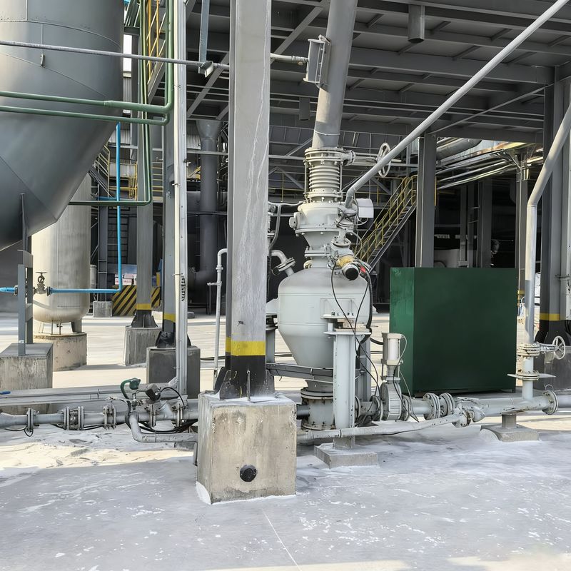
Máy bơm bể vận chuyển khí nén pha dày ∙ ∙ Máy bơm silo ∙
Thành phần cấu trúc
Đồ chính: Thông thường được cấu hình như một xi lanh thẳng đứng, với một số thiết kế ngang.thường sử dụng thép carbon Q235 hoặc thép không gỉ 304/316Các bình lớn thường được chia thành các buồng trên và dưới được tách ra bởi một nón dẫn dòng chảy hoặc tấm phân phối.với cổng đo áp suất và giao diện van an toàn được dành riêng ở phía trên hoặc bên cạnh.

Bảng tham số bơm bể vận chuyển khí nén công suất lớn
| Vật liệu vận chuyển |
Mật độ khối (t/m3) |
Mô hình |
PCD24/H |
PCD26/H |
PCD28/H |
PCD30/H |
Khoảng cách vận chuyển |
| Thông số kỹ thuật |
16~20m3 |
18~22m3 |
20~27m3 |
26~32m3 |
Mức độ (m) |
Mức độ (m) |
| Than bột |
0.5 |
Số lượng giao hàng (t/h) |
50~80 |
60~90 |
65 ~ 110 |
80~130 |
200 |
20 |
| Fly Ash |
0.75 |
75~125 |
85 ~ 130 |
95~160 |
125~190 |
200 |
20 |
| Bột đá vôi/bột khoáng chất |
0.8 |
80~130 |
90~140 |
100~170 |
130~200 |
200 |
20 |
| Xăng / Bột thô |
1 |
100~150 |
115~175 |
130~215 |
165~260 |
200 |
20 |
Bảng tham số bơm chậu vận chuyển khí nén đường dài
| Vật liệu vận chuyển |
Mật độ khối (t/m3) |
Mô hình |
PCD24/L |
PCD26/L |
PCD28/L |
PCD30/L |
Khoảng cách vận chuyển |
| Thông số kỹ thuật |
16~20m3 |
18~22m3 |
20~27m3 |
26~32m3 |
Mức độ (m) |
Mức độ (m) |
| Than bột |
0.5 |
Số lượng giao hàng (t/h) |
20~40 |
25~45 |
30~55 |
45 ~ 65 |
1000 |
25 |
| Fly Ash |
0.75 |
35~60 |
45 ~ 65 |
45~80 |
65~95 |
1000 |
25 |
| Bột đá vôi/bột khoáng chất |
0.8 |
40~65 |
45 ~ 70 |
50 ~ 85 |
70~100 |
1000 |
25 |
| Xăng / Bột thô |
1 |
50~80 |
55 ~ 90 |
65 ~ 110 |
90~120 |
1000 |
25
|
Bảng tham số bơm chậu vận chuyển khí nén lưới thông thường
| Vật liệu vận chuyển |
Mật độ lớn (bulk density)m3) |
Mô hình |
PCD18/N |
PCD20/N |
PCD20/N |
Khoảng cách truyền tham chiếu |
| Thông số kỹ thuật |
5.0~6.7m3 |
7.0~10.0m3 |
10.0~15.0m3 |
Mức độ (m) |
Dọc (m) |
| Than bột |
0.5 |
Số lượng giao hàng (t/h) |
12~20 |
16~32 |
25~50 |
500 |
30 |
| Fly Ash |
0.75 |
18~32 |
25~48 |
35~70 |
50 |
|
| Bột đá vôi/bột khoáng chất |
0.8 |
20~35 |
26~51 |
38~75 |
500 |
30 |
| Xăng / Bột thô |
1.0 |
24~42 |
32~65 |
48 ~ 95 |
500 |
30 |
| Bột silicon |
1.2 |
28~50 |
40~75 |
55~115 |
500 |
30
|
Bảng tham số của máy bơm bunker vận chuyển khí nén cỡ nhỏ
| Vật liệu |
Mật độ lớn (bulk density)m3) |
Mô hình |
PCD08/M |
PCD10/M |
PCD12/M |
PCD14/M |
Khoảng cách truyền tham chiếu |
| Thông số kỹ thuật |
0.2~0.5m3 |
0.6~1.6m3 |
1.5~2.5m3 |
2.5~5.0m3 |
Mức độ (m) |
Dọc (m) |
| Than bột |
0.5 |
Số lượng giao hàng (t/h) |
0.5~1.8 |
1.5~5.5 |
5.0~9.0 |
8.0~18.0 |
100 |
20 |
| Fly Ash |
0.75 |
0.9~2.8 |
2.5~8.5 |
7.0~14.0 |
12.0~27.0 |
100 |
20 |
| Bột đá vôi/bột khoáng chất |
0.8 |
1.0~3.0 |
3.0~9.0 |
8.0~15.0 |
12.0~28.0 |
100 |
20 |
| Xăng / Bột thô |
1.0 |
1.2~3.5 |
3.5~11.5 |
10.0~18.0 |
16.0~36.0 |
100 |
20 |
| Bột silicon |
1.2 |
1.5~4.0 |
4.5~13.5 |
12.0~20.0 |
19.0~43.0 |
100 |
20 |
Hệ thống cấp và thải
Cổng vào thức ăn thường nằm ở phía trên của bình, kết nối với các silo hoặc bộ cung cấp thức ăn phía trên, và thường sử dụng van cổng khí nén hoặc van bướm chống mòn làm van thức ăn.Các cửa ra nước được đặt ở đáy hoặc bên cạnh của bình dưới, kết nối với đường ống dẫn, và thường sử dụng van bóng gốm khí hoặc van tấm trượt cửa hai như van xả.Các bình áp suất pha dày đặc được trang bị đĩa hoặc đường ống làm lỏng ở đáy để tạo điều kiện làm lỏng vật liệu.
Hệ thống điều khiển khí
Hệ thống này bao gồm lối vào không khí nén với van điều chỉnh áp suất, các nhóm van khí nén, các thành phần phát hiện và điều khiển áp suất và các thiết bị thông gió / giảm áp suất.Không khí nén được cung cấp từ một máy nén bên ngoài và hướng qua các nhóm van khí để kích hoạt mở và đóng nguồn cấpCác yếu tố cảm biến áp suất theo dõi áp suất của bình trong thời gian thực, trong khi van van và van an toàn làm việc phối hợp để duy trì áp suất ổn định trong bình.
Thiết bị phụ trợ
Các thành phần phụ trợ bao gồm các thiết bị phát hiện mức độ, cơ chế thổi và làm sạch, và các cấu trúc hỗ trợ / khung.và một van thổi ở phía dưới cho phép loại bỏ bụi hoặc chất gây ô nhiễm tích lũyCác bình áp suất lớn thường được trang bị thang và nền tảng để dễ dàng bảo trì.
Nguyên tắc hoạt động
Quá trình vận chuyển của bình áp suất (blow tank) hoạt động theo cách chu kỳ. Ban đầu, tất cả van được đóng. Chu kỳ bắt đầu với việc mở van cung cấp và van thông hơi,cho phép bình được lấp đầy bằng vật liệu ở áp suất khí quyểnMột khi máy dò mức báo hiệu rằng bình đầy, van cung cấp và van thông hơi đóng. van không khí áp suất cao sau đó mở ra để gây áp lực cho bình.
Sau khi đạt được áp suất hoạt động, van không khí vận chuyển và van xả mở, bắt đầu vận chuyển vật liệu.van không khí áp suất cao và van xả đóngCác đường dẫn vận chuyển được thanh lọc bằng không khí nén, trong khi van thông hơi mở ra để áp suất tàu trở lại áp suất khí quyển, do đó hoàn thành một chu kỳ làm việc đầy đủ.
Các đặc điểm chính
Hiệu quả năng lượng cao: Cấu trúc làm lỏng tối ưu đảm bảo làm lỏng vật liệu tuyệt vời với mức tiêu thụ không khí thấp.
Tỷ lệ vật liệu-không khí cao: Hiệu suất làm lỏng vượt trội giảm thiểu việc sử dụng không khí, đạt tỷ lệ vật liệu-không khí vượt quá 30 kg (vật liệu) / kg (không khí).
Tốc độ vật liệu thấp: Vật liệu di chuyển theo chế độ dòng chảy cồn cát trong đường ống, dẫn đến sự mòn tối thiểu trên van và đường ống, và kéo dài tuổi thọ cho các bộ phận dễ mòn.
Khả năng quy định mạnh mẽ
Được trang bị nhiều phương tiện điều chỉnh, bao gồm điều chỉnh đầu vào không khí chính và thứ cấp, cho phép hệ thống hoạt động với tỷ lệ cung cấp không khí tối ưu và điều kiện dịch tỏa vượt trội.
Các lĩnh vực ứng dụng
Các bình áp suất (blow tank) cho vận chuyển khí nén được sử dụng rộng rãi trong các ngành công nghiệp như luyện kim, vật liệu xây dựng, chế biến ngũ cốc và thực phẩm.thu thập bụi môi trườngCác hệ thống này cho phép vận chuyển hoàn toàn kín, không bị ô nhiễm, tuân thủ các tiêu chuẩn bảo vệ môi trường.
Tại sao chọn hệ thống của chúng tôi?
Độ tin cậy vượt trội được hỗ trợ bởi sự đổi mới
• Cấu trúc thùng áp suất được cấp bằng sáng chế mang lại tuổi thọ sử dụng dài hơn 20% so với các đối tác trong ngành
• Điều chỉnh áp suất tự động thông minh đảm bảo dòng chảy vật liệu nhất quán mà không có xung hoặc tắc nghẽn
Hoạt động thông minh trực quan và kết nối
• PLC + bảng điều khiển màn hình cảm ứng ️ công thức nấu ăn có thể lưu trước để chuyển đổi nhanh giữa các vật liệu khác nhau
• Giám sát từ xa 24 giờ 7 ngày 7 ngày 7 ngày 7 ngày 7 ngày 7 ngày 7 ngày 7 ngày 7 ngày 7 ngày 7 ngày 7 ngày 7 ngày 7 ngày 7 ngày 7 ngày 7 ngày 7 ngày 7 ngày 7 ngày 7 ngày 7 ngày 7 ngày 7 ngày 7 ngày 7 ngày 7 ngày 7 ngày 7 ngày 7 ngày 7 ngày 7 ngày 7 ngày 7 ngày 7 ngày 7 ngày 7 ngày 7 ngày 7 ngày 7 ngày 7 ngày 7 ngày 7 ngày 7 ngày 7 ngày 7 ngày 7 ngày 7 ngày 7 ngày 7 ngày 7 ngày 7 ngày 7 ngày 7 ngày 7 ngày 8 ngày 8 ngày 8 ngày 8 ngày 8 ngày 8 ngày 8 ngày 9 ngày 9 ngày 9 ngày 9 ngày 9 ngày 9 ngày 9 ngày 9 ngày 9 ngày 9 ngày 9 ngày 9 ngày 9 ngày 9 ngày 9 ngày 9 ngày 9 ngày 9 ngày 9 ngày 9 ngày 9 ngày 9 ngày 9 ngày 9 ngày 9 ngày 9 ngày 9 ngày 9 ngày 9 ngày 9 ngày 9 ngày 9 ngày 9 ngày 9 ngày 9 ngày 9 ngày 9 ngày 9 ngày 9 ngày 9 ngày 9 ngày 9 ngày 9 ngày 9 ngày 9 ngày 9 ngày 9 ngày 9 ngày 9 ngày 11 ngày 11 ngày 11 ngày 11 ngày 11 ngày 11 ngày 11 ngày 11 ngày 11 ngày 11 ngày 11 ngày 11 ngày 11 ngày
Phù hợp và đáng tin cậy cho thị trường ASEAN
• Chứng nhận đôi CE & ATEX ️ đáp ứng đầy đủ các tiêu chuẩn an toàn và môi trường khu vực
• Hỗ trợ kỹ thuật tại địa phương phù hợp với các yêu cầu và quy định công nghiệp của ASEAN